Results 1 to 16 of 16

Thread: Guide: DIY Printed Circuit board Making

  1. #1
    Xtreme Member
    Join Date
    Oct 2008
    Posts
    158

    Guide: DIY Printed Circuit board Making

    DIY Printed Circuit board Making.

    Printed circuit board or PCB has its vital role in today’s high-tech life. From TV to toys from Computer to mobile, all electrons work with a PCB inside. Commonly a PCB is made up of a fiber board with copper tracks to join different electronic components together so that they can acts as a single unit or circuit. A PCB can have from a single layer of copper connection used in common electronics like toys, in pc mouse etc, or can have up to seven connection layers in single PCB used in Computer motherboard or mobile phone PCB.
    Today by this small tutorial I like to share with you the most common process of DIY PCB making at your home. I came to know this process in my school time, but one can Google and find many process of PCB making. Secondly I adopted this process because it’s very easy and low in resources. There is no proper name for this process but generally it’s called “Laser print PCB etching”.
    As the name says a laser printout is etched on a blank PCB.
    Items needed:
    1. PC and a Laser Printer (to design and printout the circuit layout).
    2. Toner Transfer Paper (to transfer the toner layout on to the PCB).
    3. Blank PCB.
    4. Hex blade, zero no. sandpaper and files (to cut the desire piece of PCB, polish and file the rough surface).
    5. Lamination Machine.
    6. Ferric Chloride and Iso-Propanol.
    7. Plastic washing tray and brushes.
    8. Drill bits to drill holes on to the PCB for component placement.
    Few WARNIGS:-
    1. Be very care full when using cutting or drilling tools. If you are not familiar with these tools better get help from a professional.
    2. Be very-very careful when working with CHEMICALS. Try not to come in direct contact with the chemical, if so immediately wash the effected body part with lot of running water.
    3. For eching process FeCl3 solution is needed. When adding H20 to FeCl3, fumes of HCL is releases which is harmful when inhaled.


    Now let’s get started. In this tutorial I am making a 4-channel Fan Controller.
    Initial circuit design and layout is done.


    Now printing the layout on to the toner transfer paper.


    Now cutting the blank PCB.


    Now use sand paper to make the PCB clean and shiny.


    Role the PCB and printout through the lamination machine, this will stick the paper onto the PCB. Now leave the PCB in soap water for an hour and then genteelly peel off the paper. Now PCB has only toner in the form of the circuit layout.


    Now it’s time to bring the chemicals in action.


    Add some distilled water in a plastic tray. (USE ONLY CHEMICAL DISTILLED WATER) battery water has some acid properly.


    Now add FeCl3 powder.


    Hot exothermic reaction, HCL fumes are librated.


    Drop the PCB in.


    Leave it for an Hour.


    Look carefully Fecl3 is eating the copper.


    After etching only toner is left.


    Clean the PCB with Iso-Propanol.


    This removes the toner and shiny copper tracks are left.


    it’s time to drill some holes. I am using 1mm drill bit and a DC motor for this job.


    Done. Your PCB is now ready to be fitted with the components.


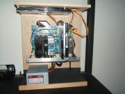
    All assembled and undergo testing. Seems everything is fine and the circuit is working perfectly.


    Some pics of final product.


    This finishes my tutorial. Hope you like it.
    I have tried my best to put this tutorial in good shape, but still please ignore any mistakes.


    Thanking
    Rakesh Sharma

  2. #2
    Xtreme Member
    Join Date
    Oct 2008
    Location
    Bologna,Italy
    Posts
    415
    very very nice guide
    sorry for my bad english
    Gigabyte Battlefield Pi 1M #3

  3. #3
    Xtreme Member
    Join Date
    Oct 2008
    Posts
    158
    Thanks Sir

  4. #4
    Xtreme Member
    Join Date
    Sep 2008
    Location
    Northeast Ohio, Canton Area
    Posts
    113
    Great guide, very similar to the method i use.
    [SIZE="1"]Main Rig:
    - New rig incoming -

    Watercooling Loop: Pump: Laing DDC 3.2 w/ XSPC Reservoir Top | Tubing: 1/2 x 3/4" | Waterblock: Apogee GTZ | Radiator: XSPC RS360 | Fans: 3x Delta FFB1212EHE | Fittings: Fatboy Barbs | Other: 5ft Custom Bong Cooler for benching

  5. #5
    Registered User transit921's Avatar
    Join Date
    Dec 2009
    Location
    nj
    Posts
    62
    i never done this before,but seams easy enough with the directions you gave,im gona give it a shot
    Last edited by transit921; 06-16-2010 at 04:59 PM.

  6. #6
    Xtreme Member
    Join Date
    Sep 2008
    Location
    Northeast Ohio, Canton Area
    Posts
    113
    something that I highly recommend when doing diy circuit boards is hitting the board with a spray of lacquer when you are finished, gives the traces a little more protection.
    [SIZE="1"]Main Rig:
    - New rig incoming -

    Watercooling Loop: Pump: Laing DDC 3.2 w/ XSPC Reservoir Top | Tubing: 1/2 x 3/4" | Waterblock: Apogee GTZ | Radiator: XSPC RS360 | Fans: 3x Delta FFB1212EHE | Fittings: Fatboy Barbs | Other: 5ft Custom Bong Cooler for benching

  7. #7
    Xtreme Member
    Join Date
    Oct 2008
    Posts
    158
    Quote Originally Posted by bomberboysk View Post
    something that I highly recommend when doing diy circuit boards is hitting the board with a spray of lacquer when you are finished, gives the traces a little more protection.
    +1. It will prevent copper oxidation. I use warnish spray for protection.

  8. #8
    Xtreme Member
    Join Date
    Jan 2010
    Location
    NY
    Posts
    147
    Very cool! Thanks for sharing
    Regards,
    Martin Simpson

  9. #9
    Xtreme Member
    Join Date
    Jul 2009
    Location
    Austin,TX
    Posts
    336
    Damn, thanks a lot man!!!

  10. #10
    Registered User
    Join Date
    May 2007
    Posts
    35
    I am gonna give it a shot.

  11. #11
    Xtreme Member
    Join Date
    Oct 2008
    Posts
    158
    Quote Originally Posted by Crys1s_Gam3r View Post
    Very cool! Thanks for sharing
    Quote Originally Posted by OverShocked View Post
    Damn, thanks a lot man!!!
    Quote Originally Posted by LittleKnown View Post
    I am gonna give it a shot.
    It's my Pleasure and thanks for reply.

  12. #12
    Xtreme Member
    Join Date
    Sep 2008
    Location
    Northeast Ohio, Canton Area
    Posts
    113
    Quote Originally Posted by rakesh_sharma23 View Post
    +1. It will prevent copper oxidation. I use warnish spray for protection.
    What program do you use to design your board layouts?
    [SIZE="1"]Main Rig:
    - New rig incoming -

    Watercooling Loop: Pump: Laing DDC 3.2 w/ XSPC Reservoir Top | Tubing: 1/2 x 3/4" | Waterblock: Apogee GTZ | Radiator: XSPC RS360 | Fans: 3x Delta FFB1212EHE | Fittings: Fatboy Barbs | Other: 5ft Custom Bong Cooler for benching

  13. #13
    Xtreme Member
    Join Date
    Oct 2008
    Posts
    158
    Auto Cad and MS Paint (win7 version)

  14. #14
    Xtreme Cruncher
    Join Date
    Jun 2008
    Location
    pacific NW usa
    Posts
    2,764
    very,very cool.thanks for the great guide.
    _________________________________________________
    ............................ImAcOmPuTeRsPoNgE............................
    [SIGPIC][/SIGPIC]

    MY HEATWARE 76-0-0

  15. #15
    Xtreme Member
    Join Date
    Sep 2008
    Location
    Northeast Ohio, Canton Area
    Posts
    113
    Quote Originally Posted by rakesh_sharma23 View Post
    Auto Cad and MS Paint (win7 version)
    That explains how clean you can get everything then, as i don't have access to autocad.
    [SIZE="1"]Main Rig:
    - New rig incoming -

    Watercooling Loop: Pump: Laing DDC 3.2 w/ XSPC Reservoir Top | Tubing: 1/2 x 3/4" | Waterblock: Apogee GTZ | Radiator: XSPC RS360 | Fans: 3x Delta FFB1212EHE | Fittings: Fatboy Barbs | Other: 5ft Custom Bong Cooler for benching

  16. #16
    Xtreme Member
    Join Date
    Oct 2008
    Posts
    158
    It's my pleasure, that you liked my effort.
    Quote Originally Posted by radaja View Post
    very,very cool.thanks for the great guide.


    There are many freewares which can help you do your PCB layout easy and clean. But i like my work done in Cad.

    Quote Originally Posted by bomberboysk View Post
    That explains how clean you can get everything then, as i don't have access to autocad.

Bookmarks

Bookmarks

Posting Permissions

  • You may not post new threads
  • You may not post replies
  • You may not post attachments
  • You may not edit your posts
  •