Page 11 of 73 FirstFirst ... 8910111213142161 ... LastLast
Results 251 to 275 of 1814

Thread: ATI 4850/4870 voltmod thread

  1. #251
    Xtreme Member
    Join Date
    Dec 2005
    Location
    Rennes (france)
    Posts
    443
    Quote Originally Posted by Theta View Post
    For anyone interested, I've played around for the last day or so with a lot of different levels of resistance. I had asked a little while back if anyone had any fixed resistor values, and nobody did.

    If anyone is interested in fixed values (assuming 1.046v IDLE / 1.084v LOAD in BIOS), here you go:

    vMEM: 100k (5&#37 
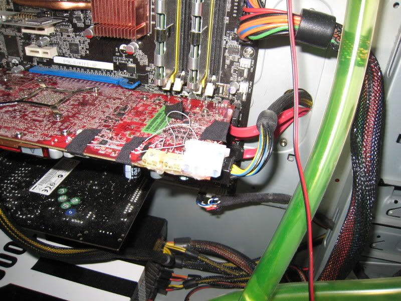
Fixed Resistor = 2.1v ~ 2.12v

    vGPU Idle: 27k (5%) Fixed Resistor = 1.17v ~ 1.20v

    vGPU Load: 27k (5%) Fixed Resistor = 1.30v ~ 1.33v


    I played around with VRs, but just wanted something solid for this round of testing. Hope this helps somebody out there...
    That's simple to know what resistance you need to get the voltage you want.

    For example : Vmem
    -Stock resistance before chip is 3.94k. Stock voltage is 2.04v.
    If you put a 100k resistance in // with the stock resistance, you get :
    Req = 1/(1/3940+1/100000) = 3.79k
    Then Vnew = Vold * Rold/Rnew = 2.04*3.94/3.79 = 2.12v

    If you want to find the resistance (Rnew) you need to set in // in order to get your new voltage (Vnew) assuming stock voltage (Vst) and stock resistance (Rst), just use this formula : 1/Rnew = Vnew/(Vst*Rst) - 1/Rst

    R in ohms and V in volts

  2. #252
    Xtreme 3D Team Member
    Join Date
    Jun 2006
    Location
    small town in Indiana
    Posts
    2,285
    I May have the V-mod for a 4870 to test, someone who owns a 4870 and a MM please PM me.

    This means someone who knows that it will void their warranty and is willing to try out the mod, I don't have a 4870 or I would test it myself.
    QX 9650 5ghz with 1.55v 4.8ghz with 1.5v 24/7 in a VAPOLI V-2000B+ Single stage phase cooling.
    DFI LP LT X-38 T2R
    2X HD4850's water cooled , volt modded
    Thermaltake 1KW Psu
    4x Seagate 250GB in RAID 0
    8GB crucial ballistix ram

  3. #253
    Xtreme Member
    Join Date
    Sep 2007
    Posts
    314
    I've got a problem. I soldered my 100k ohm resistors in the rigth place, and can overclock more, so obviously it works. However, when I try to change them so I get more voltage, no matter which dirrection I go, or how much I turn, the voltage does not change..... Anything I'm doing wrong?

  4. #254
    Xtreme Member
    Join Date
    Dec 2005
    Location
    Rennes (france)
    Posts
    443
    Shut down the PC, turn the VR and check the resitance between the 2 pad you could do a pencilmod with, it will give the reistance you have now before the chip : does it change?

  5. #255
    Xtreme Member
    Join Date
    Sep 2007
    Posts
    314
    It doesn't change.... Wth... It changed when I moved them before I hooked them up..

    Maybe I got the wrong thing... They're yellow, not blue. I'll post an image in a sec.

  6. #256
    Xtreme Member
    Join Date
    Sep 2007
    Posts
    314
    Pic. They say 64W 100k-k 9232...


    The mess gets cleaned up after I figure it all out. BUt this is weird. and I've scrued with the VRs so much that I hav no idea what resistance they're at. But still, my card is getting the proper voltage for my current overclock.

  7. #257
    Xtreme Enthusiast
    Join Date
    Nov 2006
    Location
    Poland / Rypin
    Posts
    865
    wesley

    like this ?

    Schedule of Live Extreme Overclocking - info Thread

    Quote Originally Posted by K404 View Post
    "My Backup is bigger than Your Backup"

  8. #258
    Registered User
    Join Date
    Jun 2008
    Posts
    36
    @fatalbert, that is exactly correct. Just make sure you turn the Trimpots to maximum resistance before you power up. Measure them with a Digital Multimeter. Depending on which way you want to turn the dial on the Trimpot, you could connect the outside wire on the other side.

  9. #259
    Xtreme Enthusiast
    Join Date
    Nov 2006
    Location
    Poland / Rypin
    Posts
    865
    it's not for me

    thanks for the advice
    Schedule of Live Extreme Overclocking - info Thread

    Quote Originally Posted by K404 View Post
    "My Backup is bigger than Your Backup"

  10. #260
    Registered User
    Join Date
    Dec 2007
    Posts
    61
    Damn.. testing atm - my card wont even do 825 @ 1,45v...
    -------------------

    Laptops and gaming is like riding a tricycle through Tour de France..

  11. #261
    Xtreme Member
    Join Date
    Sep 2007
    Posts
    314
    Fixed. Didn't realize how many turns it took to actually get the damned things to go down in resistance

  12. #262
    Registered User
    Join Date
    Dec 2007
    Posts
    61
    Ok - checked the vGPU. Somethings is wrong, it shows 1,2v
    -------------------

    Laptops and gaming is like riding a tricycle through Tour de France..

  13. #263
    c[_]
    Join Date
    Nov 2002
    Location
    Alberta, Canada
    Posts
    18,728
    That happens when you use VR's that are too high resistance (adpr_02).

    Wheelman - what VR did you use?

    All along the watchtower the watchmen watch the eternal return.

  14. #264
    Registered User
    Join Date
    Dec 2007
    Posts
    61
    BIOS-mod - 1,45v (+ a small pencilmod, 4,77ohm)
    -------------------

    Laptops and gaming is like riding a tricycle through Tour de France..

  15. #265
    Xtreme Member
    Join Date
    Dec 2005
    Location
    Rennes (france)
    Posts
    443
    Did you really measure 1.45v with a DM?

    Here's a really simple excel tool to know the resulting Voltage and/or the needed resistance : Link. When enterred values aren't correct, the corresponding cases are blank.

  16. #266
    Registered User
    Join Date
    Jun 2008
    Posts
    46
    Quote Originally Posted by wesleyclark View Post
    yeah, i found pretty much the cheapest DMM i could find at radioshack. Its a shame they wont just put a AA on it or something and be nice to us. As for the iron, the reason i got the 15, was so that i wouldn't melt things. I didn't think to try using a little new solder to melt the old. Ill try that once i replace my lost solder tonight.
    Its not that you are trying to melt the old... Its that you don't need to. (at least I think...) You would just need to solder the new wire, etc down to that point by melting the new solder, I think you would lay down the new solder first then the wire and more solder.. its so you have 'glue' on either side so to speak. At least I think this is how... (please someone correct me if I am wrong)

    I would anticipate on something like that card, the solder they would use would have a higher melting point then the little stuff you'll use to tack your wire down to it with. Mainly because its done in a large industrial setting, and ofttimes has to bind components onto the pcb... Further, it'll be designed to take a huge thermal load over and over and over again... So I doubt they'd have used something like what you will be for the little mod.

    So correct me if I am wrong... but you aren't meant to, and don't need to melt the existing solder points. Instead your soldering something onto it... and as such, only need to melt your solder so it 'sticks' to the existing point and holds your wire in place with good electrical conductivity.

  17. #267
    Registered User
    Join Date
    Dec 2007
    Posts
    61
    Quote Originally Posted by Clemmaster View Post
    Did you really measure 1.45v with a DM?
    No, i set 1,45v in the BIOS-mod program.

    Gave it up - pencilmodding atm, 60*C max at 1,35v stock speed, 3,88Ohm (just testing max voltage).
    2,8ohm wouldn't boot, lol.
    -------------------

    Laptops and gaming is like riding a tricycle through Tour de France..

  18. #268
    Registered User
    Join Date
    Mar 2007
    Location
    Sweden
    Posts
    79
    I'd recommend anyone who is planning on soldering to read through this guide first.
    CM Stacker STC-T01, Corsair HX620, ASUS P5Q-Deluxe, E8400 E0 @4.05/1.375v,
    Crucial Ballistix PC6400 @560/5-5-5-18/2.1v, HIS HD4870 w/ vmod.


    Laing D5 + EK X-TOP , D-TEK Fuzion w/ 4.5mm nozzle, D-TEK Fuzion GFX w/ "Saltshaker" mod,
    Thermochill PA120.3, 1/2" 3/4" Tygon B-44-4X.

  19. #269
    Registered User
    Join Date
    Dec 2007
    Posts
    61
    Got the cards up to 1,63v load - just flashed to 1000/1100

    Results tomorrow
    -------------------

    Laptops and gaming is like riding a tricycle through Tour de France..

  20. #270
    c[_]
    Join Date
    Nov 2002
    Location
    Alberta, Canada
    Posts
    18,728
    Quote Originally Posted by darkskypoet View Post
    Its not that you are trying to melt the old... Its that you don't need to. (at least I think...) You would just need to solder the new wire, etc down to that point by melting the new solder, I think you would lay down the new solder first then the wire and more solder.. its so you have 'glue' on either side so to speak. At least I think this is how... (please someone correct me if I am wrong)

    I would anticipate on something like that card, the solder they would use would have a higher melting point then the little stuff you'll use to tack your wire down to it with. Mainly because its done in a large industrial setting, and ofttimes has to bind components onto the pcb... Further, it'll be designed to take a huge thermal load over and over and over again... So I doubt they'd have used something like what you will be for the little mod.

    So correct me if I am wrong... but you aren't meant to, and don't need to melt the existing solder points. Instead your soldering something onto it... and as such, only need to melt your solder so it 'sticks' to the existing point and holds your wire in place with good electrical conductivity.
    "Cold joints" suck.

    You should preferrably melt both the old and new otherwise the joint will be exceedingly weak and may cause resistance or no connection.

    All along the watchtower the watchmen watch the eternal return.

  21. #271
    Xtreme Member
    Join Date
    Aug 2007
    Posts
    370
    Quote Originally Posted by darkskypoet View Post
    Its not that you are trying to melt the old... Its that you don't need to. (at least I think...) You would just need to solder the new wire, etc down to that point by melting the new solder, I think you would lay down the new solder first then the wire and more solder.. its so you have 'glue' on either side so to speak. At least I think this is how... (please someone correct me if I am wrong)

    I would anticipate on something like that card, the solder they would use would have a higher melting point then the little stuff you'll use to tack your wire down to it with. Mainly because its done in a large industrial setting, and ofttimes has to bind components onto the pcb... Further, it'll be designed to take a huge thermal load over and over and over again... So I doubt they'd have used something like what you will be for the little mod.

    So correct me if I am wrong... but you aren't meant to, and don't need to melt the existing solder points. Instead your soldering something onto it... and as such, only need to melt your solder so it 'sticks' to the existing point and holds your wire in place with good electrical conductivity.

    You definitely want to melt the existing solder. Sometimes melting new solder can help the old melt, but what you're describing won't hold.

    The traces around the smaller mod points on the board melt easily w/ a 15W iron, but the read points which have a much larger amount of metal around them are harder to heat up. The extra metal wicks up the heat from the iron, and makes it difficult to melt the solder.

    You may be right about the solder having a higher melting point on the board, though, b/c it is lead-free. Nevertheless you want the all the solder w/n the joint to melt and run free. You can usually see it 'drop' when it has become 1.

    I've started using 2 irons. I use my trusty 15W w/ custom sharpened tip for the finer work, and an adjustable 50W iron for the stuff that doesn't melt quickly w/ the 15W iron.
    ES Q9550 E0 @ 4.0GHz (471x8.5) 1.256v
    TR-Ultra-120-X, 115CFM 120mm fan
    Maximus II Formula @ 1884MHz FSB
    Ballistix DDR2-800 (4x1GB) 1132MHz 5-5-5-5-15 4-55-8-14-11-3-8-5-4-2T
    eVGA GTX 280 @ 702c/1404s/1260m (1.175v)

    Auzentech XPlosion DTS-Interactive Vantage 'X'-6,727
    300GB Velociraptor, PC P&C 750W
    (3)120mm, (2)90mm, (1)250mm case fans in TT Armor

    27.5" LCD/Z-5500-office, 95" 720P projector/7.1ch-living room
    Logitech Driving Force Pro-Microsim Racing Pod

  22. #272
    Registered User
    Join Date
    Jun 2008
    Posts
    46
    See really needed to be corrected and it makes sense to want to melt the two together... But for some of it... 15w might take a while. I get what you mean about the weakness of a cold joint, makes sense. I better check out that guide ... although I think i'll pencil mod for now.

  23. #273
    Xtreme Member
    Join Date
    May 2006
    Posts
    187
    if any of you guys have GRID, can you test your overclock with it? I tried ATI tool stress test, and it was fine, i am retrying crysis to see if it loads the card more, but no matter what i do when i get into GRID the game shuts off my video card! I did flash to get 750 mhz but shouldnt it be stable at 1.2v????? unless im not getting 1.2 from the bios flash. I tried 725mhz in GRID and it too failed. The only thing i have overclocked is the core and its cooled by an S1, the ram dont have heatsinks on them yet but will very soon. Before i flashed, it would do it at 700mhz too, so im going to test it out at 700 see if it crashes. This sucks ass!

  24. #274
    Xtreme Enthusiast
    Join Date
    Dec 2003
    Location
    Nederlands
    Posts
    635
    What kind of increase did you guy's see when going from 2.0 to 2.1v on the memory chips ? In the past the clocks went down when increasing the voltage. Because the boards where already running the chips to the max. Lowering the voltage sometimes gave a increase.

    I'm thinking about v-modding my HD4850. But i'm also thinking of buying a HD4870. Those things have 1.26v on the core stock. And run like 790 MHz (max CCC) without a problem. I dont see my HD4850 with running 800 MHz with just 1.26v.
    System Specs: -=Game PC=- | -=Lan Box=-

  25. #275
    Xtreme Member
    Join Date
    May 2006
    Posts
    187
    Well im sure it can. Gurusan did it.

Page 11 of 73 FirstFirst ... 8910111213142161 ... LastLast

Bookmarks

Bookmarks

Posting Permissions

  • You may not post new threads
  • You may not post replies
  • You may not post attachments
  • You may not edit your posts
  •