Page 70 of 73 FirstFirst ... 206067686970717273 LastLast
Results 1,726 to 1,750 of 1814

Thread: ATI 4850/4870 voltmod thread

  1. #1726
    Registered User
    Join Date
    Dec 2009
    Posts
    5
    Quote Originally Posted by Aragarn View Post

    So the resistor i need to shade is R685 ? on other pictures i saw is r1687 like in this picture :http://yfrog.com/gi4850shphj the bord was a 4850 sapphire
    and also same card a person told him to do like in this picture http://yfrog.com/5bvmodareawm9j
    but the guy shade the r1687 resistor and it worked like in the 1st picture ! Also for the stock PCb the read of scheme is not like in this picture ??http://yfrog.com/jv4850stockj
    Maybe im wrong but if im not the r1687 resistor is shade !! Thanks for your Help
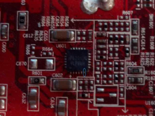
    QUOTE : CL3P20 Hmm..do you have a DMM to see if the resistors are connected, I cannot make out the paths visually from the pics, and have sold my 4850's. The R685 is just adjacent to the location the other users mod'd from..they could be connected..

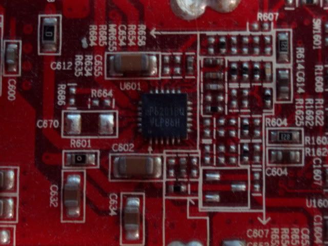
    The resistor R 685 and R 1687 and not connected ... so my question is what is hte resistor i need to shade ? R685 or r 1687 ?? Can any1 check my links with pictures to confim whats the resistor you need to shade on the stock PCB ?

  2. #1727
    Registered User
    Join Date
    Dec 2009
    Posts
    5
    On other tutorial you can shade like here to get more voltage on the gpu


    IS the place you need to shade R650 like in this picture ?


    On my VGA i have the r650 resistor (is the resistor ) not a free space , should i shade that ?? Il appreciate any ideas and Help ! Thanks

  3. #1728
    Registered User
    Join Date
    Jan 2009
    Location
    Australia
    Posts
    9
    I got a Powercolor 4850 1GB and it has a version of the uP6201BQ that doesn't have a mod. The writing underneath uP6201BQ is VLP 86H.

  4. #1729
    Xtreme Enthusiast
    Join Date
    Dec 2005
    Location
    Estonia, Tartu
    Posts
    889
    DavyGT, nothing is different. FB pin is still pin #13. Trace it and find a good soldering point. Measure default FB->GND resistance and You'll have Vmod.
    Vmods - what can possibly go wrong? ©

  5. #1730
    Registered User
    Join Date
    Jan 2009
    Location
    Australia
    Posts
    9
    Quote Originally Posted by ceemic View Post
    DavyGT, nothing is different. FB pin is still pin #13. Trace it and find a good soldering point. Measure default FB->GND resistance and You'll have Vmod.
    I already found pin 13 but how do I trace it?

  6. #1731
    Xtreme Enthusiast
    Join Date
    Dec 2005
    Location
    Estonia, Tartu
    Posts
    889
    No, that's #6. See one post above Your previous post here. There is FB marked with green.


    EDIT: should be this trace:

    That pic is not that good, so I can be wrong. You can confirm it with DMM.
    Last edited by ceemic; 07-25-2010 at 02:23 AM.
    Vmods - what can possibly go wrong? ©

  7. #1732
    Registered User
    Join Date
    Jan 2009
    Location
    Australia
    Posts
    9
    Quote Originally Posted by ceemic View Post
    No, that's #6. See one post above Your previous post here. There is FB marked with green.


    EDIT: should be this trace:
    Image
    That pic is not that good, so I can be wrong. You can confirm it with DMM.
    I measured it with a DMM and I get 0 Ohms for it.

  8. #1733
    Registered User
    Join Date
    Sep 2008
    Location
    Ukraine
    Posts
    44
    Hi guys!
    I have a problem understanding the layout of my non-reference ASUS 4850. It is ssame as this one.
    Ceemic, you suggest to measure vGPU on the capacitors:

    But the voltage I measure between the positive and negative leads of the capacitor is about 0.1V higher than it should be. Even more so, the voltage between the pos and neg leads of the cap is significantly different from the voltage between pos lead of the cap and ground wire of the molex connector.
    And I can tell for sure (judging by the temperature and OC) the voltage I've measured isn't vGPU. Where can I find the right voltage?
    Thanks in advance.
    P.S. I've checked my DMM, it's error doesn't exceed 1% when measuring 1.3V

  9. #1734
    Xtreme Enthusiast
    Join Date
    Dec 2005
    Location
    Estonia, Tartu
    Posts
    889
    DavyGT. If resistance between FB pin and that point on that SMD cap is 0ohm, then yes, they are connected and You can use that spot for soldering. Now measure resistance between FB and GND.
    Vmods - what can possibly go wrong? ©

  10. #1735
    Xtreme Enthusiast
    Join Date
    Dec 2005
    Location
    Estonia, Tartu
    Posts
    889
    @lex, why do You measure Vgpu between cap legs? Ofc You have to use a proper GND.
    Vmods - what can possibly go wrong? ©

  11. #1736
    Registered User
    Join Date
    Jan 2009
    Location
    Australia
    Posts
    9
    Quote Originally Posted by ceemic View Post
    DavyGT. If resistance between FB pin and that point on that SMD cap is 0ohm, then yes, they are connected and You can use that spot for soldering. Now measure resistance between FB and GND.
    I have measured resistance between 3 PCIE Ground Pins and a screw holding the cooler.
    2 of the PCIE Ground pins and the screw shows a resistance of 3.86 Ohms on the 20k scale.
    The last PCIE Ground Pin gets nothing.
    Also, I have found that capacity to connected to 2 resistors. Does that count as a pencil mod?
    Edit: How do I find the VGPU read points?
    Last edited by DavyGT; 07-25-2010 at 03:23 AM.

  12. #1737
    Registered User
    Join Date
    Sep 2008
    Location
    Ukraine
    Posts
    44
    ceemic, thanks, my bad. I was absolutely sure the other leg has to be ground. But still, readings between the positive leg of cap and the ground from PSU are too high. Where can I find proper ground on the PCB?

  13. #1738
    Xtreme Enthusiast
    Join Date
    Dec 2005
    Location
    Estonia, Tartu
    Posts
    889
    DavyGT, then You can use 100k ohm VR.
    It depends to what these resistors are connected. I never use pencil-mods and don't recommend it.
    For Vgpu You can use PWM cap legs for example. Similar to: http://ceemic.pri.ee/hardware/hd4850..._mod01_mon.jpg
    Do a layout pic so we can suggest the best place for measuring.
    Vmods - what can possibly go wrong? ©

  14. #1739
    Xtreme Enthusiast
    Join Date
    Dec 2005
    Location
    Estonia, Tartu
    Posts
    889
    @lex, there is no difference between molex GND or GND near IC; maybe ~0,005V.
    Vmods - what can possibly go wrong? ©

  15. #1740
    Registered User
    Join Date
    Sep 2008
    Location
    Ukraine
    Posts
    44
    Quote Originally Posted by ceemic View Post
    @lex, there is no difference between molex GND or GND near IC; maybe ~0,005V.
    I know there shouldn't be any difference, but the stock voltage of 1.25V doesn't feel right. I don't know what's wrong with this card...

  16. #1741
    Registered User
    Join Date
    Jan 2009
    Location
    Australia
    Posts
    9
    Quote Originally Posted by ceemic View Post
    DavyGT, then You can use 100k ohm VR.
    It depends to what these resistors are connected. I never use pencil-mods and don't recommend it.
    For Vgpu You can use PWM cap legs for example. Similar to: http://ceemic.pri.ee/hardware/hd4850..._mod01_mon.jpg
    Do a layout pic so we can suggest the best place for measuring.
    I don't have a series of capacitors on my card. All my card's capacitors are near the PWM.

  17. #1742
    Xtreme Enthusiast
    Join Date
    Dec 2005
    Location
    Estonia, Tartu
    Posts
    889
    @lex, why it can't be 1,25V? Sounds pretty ok. Sadly I don't remember my different HD4850's def Vgpus.
    Vmods - what can possibly go wrong? ©

  18. #1743
    Xtreme Enthusiast
    Join Date
    Dec 2005
    Location
    Estonia, Tartu
    Posts
    889
    DavyGT, try these:
    Vmods - what can possibly go wrong? ©

  19. #1744
    Registered User
    Join Date
    Jan 2009
    Location
    Australia
    Posts
    9
    Quote Originally Posted by ceemic View Post
    DavyGT, try these:
    My DMM reads 1.21v at load, so they look like the VGPU read points. My BIOS has the 1.158v edit already so it looks like it is it.

  20. #1745
    Registered User
    Join Date
    Sep 2008
    Location
    Ukraine
    Posts
    44
    Quote Originally Posted by ceemic View Post
    @lex, why it can't be 1,25V?
    Not that it's impossible, but both overclock and temps are very much the same as my reference 4850 had on 1.15V. That's why I think 1.25 isn't really vGPU. if it is, then I got incredibly bad card (720 MHz at >1.3V), which is doubtful.

  21. #1746
    Xtreme Enthusiast
    Join Date
    Dec 2005
    Location
    Estonia, Tartu
    Posts
    889
    @lex, my Asus HD4850 was also very bad clocker. It's probably due to the custom PCB/PWM...
    Vmods - what can possibly go wrong? ©

  22. #1747
    Registered User
    Join Date
    Sep 2008
    Location
    Ukraine
    Posts
    44
    ceemic, thanks for info! I'll try to swap my card for reference, then.

  23. #1748
    Registered User
    Join Date
    Jun 2007
    Location
    Srbija Vojvodina Pancevo
    Posts
    81
    @ceemic
    I have a short circuit but OCP is not disable
    http://i220.photobucket.com/albums/d...5388_OCP_m.jpg
    No volts, no nothing

    [SIGPIC][/SIGPIC]

  24. #1749
    Xtreme Enthusiast
    Join Date
    Dec 2005
    Location
    Estonia, Tartu
    Posts
    889
    D0m|nat0R, how do You know OCP is "kicking" in?
    Vmods - what can possibly go wrong? ©

  25. #1750
    Registered User
    Join Date
    Jun 2007
    Location
    Srbija Vojvodina Pancevo
    Posts
    81
    work on 2D with 1.4 1.5V but in 3D kicking to 0V all over 1.3 1.35
    Last edited by D0m|nat0R; 07-25-2010 at 09:55 AM.
    No volts, no nothing

    [SIGPIC][/SIGPIC]

Page 70 of 73 FirstFirst ... 206067686970717273 LastLast

Bookmarks

Bookmarks

Posting Permissions

  • You may not post new threads
  • You may not post replies
  • You may not post attachments
  • You may not edit your posts
  •