

Thanks for reply , i will measure the resistance later today when i get back home .
I have tried this mod since the author confirmed that it work on palit sonic video card same design as mine (check post #1164) , but the card was the HD 4850 sonic.


Thanks for reply , i will measure the resistance later today when i get back home .
I have tried this mod since the author confirmed that it work on palit sonic video card same design as mine (check post #1164) , but the card was the HD 4850 sonic.
2600K working in 4.8 GHZ so far
2600k @(4600Ghz) 1.42v : (under water)
Asus B2 mobo
4 GiG DDR 2400 MHZ
GTX 570 @ 1.063v ( 910/1820/2001 Mhz) .(under water).
1020 W PSU
Hobie's : Overclocking .... Overclocking .... Overclocking
celemine1Gig thanks for your support.
messured resistance between
pin 1 - 19 = 10.06 k
pin 14 -19 = 9.75 k
2600K working in 4.8 GHZ so far
2600k @(4600
Asus B2 mobo
4 GiG DDR 2400 MHZ
GTX 570 @ 1.063v ( 910/1820/2001 Mhz) .(under water)
1020 W PSU
Hobie's : Overclocking .... Overclocking .... Overclocking

I would recommend either 2 200k potentiometers connected in series (resulting resistance of 400k), or alternatively a single 500k (or at least! a 200k) potentiometer. Keep in mind that the latter will have less precision in lower resistance (=higher voltage) ranges.
Anything less, concerning the total resistance, would give too much of a default voltage bump IMHO.
Set (all) the potentiometer(s) to their/its max. resistance and connect them/it bewteen pin#19 and pin#14. That should work. Maybe you got a black screen because you hit the OVP voltage limit. Then you could consider yourself lucky.
BTW: What the heck does that mean "50 h vr"?
And another thing:
I'm sorry, if this sounds rude, but do you even remotely know what you are doing?Originally Posted by makaka

Why would you want to measure resistancee between pin#1 and pin#19, which correspond to "EN" and "Vfb"? What do you think has the "Enable" pin to do with the feedback in terms of a vmod.
Last edited by celemine1Gig; 05-11-2009 at 02:54 AM.
Quote from one of our professors:
"Reality is hiding in the imaginary part."
HI there ;
i will try with 2 x 200k or 500 k potentiometers ,
i meant 50 k potentiometersBTW: What the heck does that mean "50 h vr"?
No i don't know :-) , i just saw a post above asking for the resistance between those so i measured it , may be it will be useful for u .I'm sorry, if this sounds rude, but do you even remotely know what you are doing?
Also can i solder to other points since the pins are pretty hard for my low soldering skills ,
If yes please show them in the picture above .
Also were can i check the vcore , (i tried those)
they show 1.28v 2d and 1.33v (3d) , note with video card turbo button on .
never checked with the normal mod
Last edited by makaka; 05-11-2009 at 06:27 AM.
2600K working in 4.8 GHZ so far
2600k @(4600
Asus B2 mobo
4 GiG DDR 2400 MHZ
GTX 570 @ 1.063v ( 910/1820/2001 Mhz) .(under water)
1020 W PSU
Hobie's : Overclocking .... Overclocking .... Overclocking
Try using the empty solder pads to the right, that would normally be occupied by some SMD capacitors. That's a better place to measure the real VGPU, because it is behind the inductors and not before them, like the points you marked.
And concerning VMem: One of the two AWP7065 probably regulates the memory voltage. Question's just which one (I would guess that it's the upper one).Some esaurements should clear that up.
Quote from one of our professors:
"Reality is hiding in the imaginary part."
HI there , Thanks for reply .
The vmem is not required
Also can i solder (vgpu mod) to other points since the pins are pretty hard for my low soldering skills ,
If yes please show them in the picture above .
2600K working in 4.8 GHZ so far
2600k @(4600
Asus B2 mobo
4 GiG DDR 2400 MHZ
GTX 570 @ 1.063v ( 910/1820/2001 Mhz) .(under water)
1020 W PSU
Hobie's : Overclocking .... Overclocking .... Overclocking
Of course you can use different solder points, as long as they are directly connected to the named pins. And I won't mark them as I can't test the electrical connection. You can do that. It really isn't very complicated.
Quote from one of our professors:
"Reality is hiding in the imaginary part."
thanks i will do it
2600K working in 4.8 GHZ so far
2600k @(4600
Asus B2 mobo
4 GiG DDR 2400 MHZ
GTX 570 @ 1.063v ( 910/1820/2001 Mhz) .(under water)
1020 W PSU
Hobie's : Overclocking .... Overclocking .... Overclocking
HI there ;
After checking i found that the pin 14 is not directly connected to any other point . this is clear from the PCB pic ,
so even if not directly connected can i solder to it ?
2600K working in 4.8 GHZ so far
2600k @(4600
Asus B2 mobo
4 GiG DDR 2400 MHZ
GTX 570 @ 1.063v ( 910/1820/2001 Mhz) .(under water)
1020 W PSU
Hobie's : Overclocking .... Overclocking .... Overclocking

pin14 probably "dives" into PCB where it's connected to GND. So You have to use some other GND point near that IC. celemine1Gig might know it better...
Vmods - what can possibly go wrong? ©
Thanks for reply , will any GND point work ?or it has to be near the IC , In theory any GND will work but go figure , this is why i am asking
2600K working in 4.8 GHZ so far
2600k @(4600
Asus B2 mobo
4 GiG DDR 2400 MHZ
GTX 570 @ 1.063v ( 910/1820/2001 Mhz) .(under water)
1020 W PSU
Hobie's : Overclocking .... Overclocking .... Overclocking
Yep, normally any GND point should work. The best option would be to use a point directly connected to AGND, as this is the real reference for the feedback line, but as AGND and GND shouldn't differ by much (AGND should be less prone to interference), it should theoretically not matter at all if you used just GND instead. The difference between GND and AGND as reference should max. be in the mV range.
Quote from one of our professors:
"Reality is hiding in the imaginary part."
Thanks just done the Vmod
Thanks again for your help
2600K working in 4.8 GHZ so far
2600k @(4600
Asus B2 mobo
4 GiG DDR 2400 MHZ
GTX 570 @ 1.063v ( 910/1820/2001 Mhz) .(under water)
1020 W PSU
Hobie's : Overclocking .... Overclocking .... Overclocking
And now post a highres picture with your exact solder points, for other poeple with the same card, as reference.I mean, I know how to work out mods, but others obviously don't, so this way you can give something back to the community.
Maybe you can even put all the needed info + pic in one final posting, so one can link to that one posting in case someone's gonna ask for the mod in the future.
Quote from one of our professors:
"Reality is hiding in the imaginary part."
will do it when i will get back home
2600K working in 4.8 GHZ so far
2600k @(4600
Asus B2 mobo
4 GiG DDR 2400 MHZ
GTX 570 @ 1.063v ( 910/1820/2001 Mhz) .(under water)
1020 W PSU
Hobie's : Overclocking .... Overclocking .... Overclocking
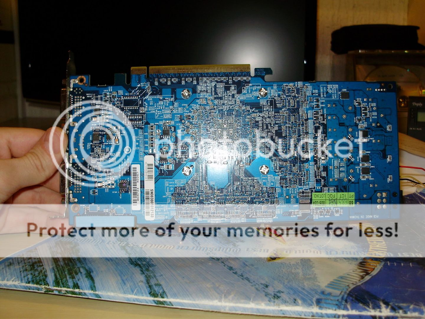
First i want to thanks celemine1Gig and ceemic for their help finding the right vmod for the HD 4870 Palit soic edition (dual bios and dual fan) ,
here is the video card picture :
The vmod for the card and the vcore measure points :
Here is some result using 2 Gb ram (470 mhz) , E8500 @ 4.2 Ghz (470x9) , p5q , 1000w psu , raid 0 :
Note : stock volt according to point above was 1.335 v (maybe palit over volted the card ). the card max stable was 800 mhz GPU and 1050 GDDR5
@ 1.44 v (load) 900 Mhz stable
@ 1.44 v (load) 920 Mhz
@ 1.44 (load) 940 Mhz
@1.5v (load) 950 Mhz
@ 1.55v (load) 960 Mhz
@ 1.6v (load) XXX??? dark screen with restart GPU voltage show -0.03 v maybe a rest or OVP ,
975 also passed the test @ 1.55v but there was a lot of artifact , so i decided to not publish the result .
Any OVP mod for my card , i am looking for 1000 Mhz benchable
Last edited by makaka; 05-16-2009 at 06:51 AM.
2600K working in 4.8 GHZ so far
2600k @(4600
Asus B2 mobo
4 GiG DDR 2400 MHZ
GTX 570 @ 1.063v ( 910/1820/2001 Mhz) .(under water)
1020 W PSU
Hobie's : Overclocking .... Overclocking .... Overclocking
makaka, 960MHz is very good OC
Vmods - what can possibly go wrong? ©
Still need more , i looked for 1000 Mhz
2600K working in 4.8 GHZ so far
2600k @(4600
Asus B2 mobo
4 GiG DDR 2400 MHZ
GTX 570 @ 1.063v ( 910/1820/2001 Mhz) .(under water)
1020 W PSU
Hobie's : Overclocking .... Overclocking .... Overclocking
The OVP mod would probably include cutting one trace. To decrease the 1.3V limit at pin#17 (DIFFOUT), one would have to increase resistance between Vfb (pin#19) and DIFFOUT, in order to decrease the voltage at diffout. Probably not worth the effort as ~1.6V is very high already. I'd rather say that perhaps some other mods. Better filtering VGPU could help get another extra MHz. Sometimes, voltage alone isn't really that helpful.
Quote from one of our professors:
"Reality is hiding in the imaginary part."
well what should be safe VGPU then for 24/7 usage under water , (40- 44 c load) ?
2600K working in 4.8 GHZ so far
2600k @(4600
Asus B2 mobo
4 GiG DDR 2400 MHZ
GTX 570 @ 1.063v ( 910/1820/2001 Mhz) .(under water)
1020 W PSU
Hobie's : Overclocking .... Overclocking .... Overclocking
Is there a pencil vgpu mod for the XFX 4850? I've found the mod thread, but it only has the solder mod. TIA.
1.4 is pretty safe for 24/7 overclock
more than 1.5 you will degrade the card :/
i killed one 4850 and one 4870 @ 1.5 ( core artifacts ) and the were at 35*C load
CPU : Q9550 / Board : Asus P5E64 WS Evolution / Ram : 2x1 OCZ D9GTR DDR3 / Vga : HD 4870 / PSU : PPC&C 750W / SSD Ocz Vertex 30Gb / All under Water & Tec's
Overclockers Wannabe Athens Dept...
Hello
Is there a pencil vgpu mod for the Gigabyte 4850 512mb? Or soldering mod?
Here are the pictures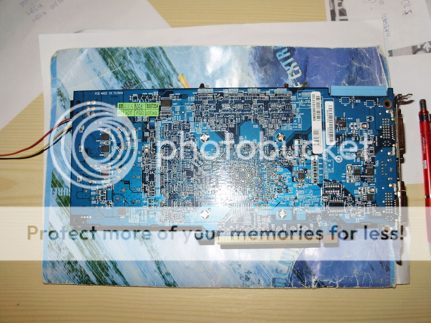

Last edited by John S.; 05-25-2009 at 02:40 PM.
Intel C2D E5200@3200Mhz 1.35V+Scythe Ninja 2
Gigabyte EP35-DS3+Thermalright HR-05-SLI
2x2gb Kingmax 800MHz
Sapphire 4870 1Gb+Accelero S1
Seasonic S12II 430W
Seagate 250GB+Samsung Spinpoint F1 1TB
Samsung 2233BW
Hi guys!
Have you figured out another vcore pencil-mod for this card as well?
Please let me know if you do!
Yours // fng77
MotherBoard: GigaByte G33M DS2R
Memory: 2x1 Gb HyperX DDR2-9600, 1200 Mhz
Cpu: Intel e2160 @ 3,6 Ghz on Air
Vga: XFX 4870 XXX
Cooling: Ninja Mini, 2x Ximatek 120mm, 1x Zalman 80mm, Stock Gpu
Case: Antec Fusion Remote
I have the same card, but I don't have the proper tools to do the mod. All I can afford to do ATM is a pencil mod.
Would a pencil mod be possible on this card?
Thanks!
 Posting Permissions


 Reply With Quote


Bookmarks