Page 1 of 3 123 LastLast
Results 1 to 25 of 69

Thread: My tec liquid chiller project

  1. #1
    Registered User
    Join Date
    Apr 2008
    Posts
    85

    My tec liquid chiller project

    I've kept up with computer technology and hardware for about 10 years
    but never built my own until February. I went into it whole hog - water cooling
    and overclocking. It didn't take me long to start thinking about sub-ambient
    cooling. Obviously, the main difficulty in cooling a processor is the fact that
    150+ watts are being generated in area less than 1.5 sq inches ( high overclocks ).
    Phase change gets the job done, but involves skills that I don't
    possess ( I'm an electrician, not a HVAC guy ). So, I gravitated towards TECs.
    I decided that the best results would come from building a liquid chiller
    using multiple TECs. After deciding on my design, I found this part of the
    forums, which has given me additional information .

    Here is my design:

    One 12" x 1.75" copper chamber mounted to the cold side of the
    TECs that is part of the cooling loop of the processor.

    Two 12" x 2" copper chambers mounted on the hot side of the
    TECs and part of the cooling loop for the TECs.

    Two PA 120.3 with Sanyo Denki fans to cool the TECs.

    Blueline 30HD pump for the hotside loop.

    PDD-20 pump (rebadged Iwaki MD 20) and 24volt power supply
    for the coldside loop.

    Two server PSUs for power

    14 TEC1-12706 tecs

    I was going to use 10 TECs in an attempt to get the best temps and stay
    under 600 watts used, but right before assembly I decided to add 4 more
    TECs ( I had enough room for them and enough power ).

    Here are some pictures:


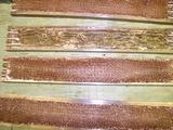
    These are the copper bars I used. Four of the bars are 3/8" thick and two are
    3/16" thick.


    I used a hand-me-down Black&Decker router and a two flute spiral cut router bit to make the chambers.


    I had some trouble at first keeping the depth consistent with that cheap router, but on average,
    the dimensions of the middle chamber is 11.5" x 1.5" x 3/8"
    deep, and for the outer chambers it's 11.5" x 1.5" x 3/16" deep.


    To improve the heat transfer coefficient of my chiller, I inserted copper mesh in each chamber.


    I applied silver-bearing solder paste on the inside of the chambers in order
    to improve the heat flow into/out of the copper mesh.


    I clamped each chamber and applied heat ( propane burner
    and a thick aluminum griddle to act as a heat spreader )
    and soldered the halves of the chambers together.
    It was difficult ( little experience at soldering ) and not completely successful.


    All three chambers have three 1/4" tubes on each end and with a 1/2" copper stubout soldered on each end.


    Here is one of the chambers after some sanding ( I had to do much more sanding to get them flat enough ).
    The gray stuff is JB weld, which is necessary
    to seal the various leaks that appeared when I did a leak test.


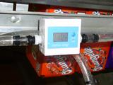
    This is a test run on the hotside loop to check out how much flow
    it will have.


    As you can see, the flow is a bit uneven between the two parts of the
    loop. Also, the flow is a touch lower then I had hoped for ( I wanted
    about 2.0 gallons a minute), but I think it will be enough. According
    to Martin's test on the PA120.3 and with the fans I am going to use,
    the air in / water out delta should be no more than 7 to 8 deg Celsius.


    This the test run on the coldside loop. I used an apogee gt and an apogee
    gtx to simulate, the best I could, a more restrictive block.


    By adjusting the potentiometer on the Meanwell 24 volt power supply,
    I could vary the flow rate from 1.29 gal/min to 1.72 gal/min.


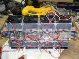
    Here are a couple of pictures of the chiller assembled. I had to figure out
    how to sandwich the TECs and chambers together, and I had these
    heatsinks that I got cheap off of eBay, so I decided to use them on
    the hot side also. Using the info that Uncle Jimbo gave on how to apply
    enough force to the TECs, I think that I have about 250 lbs per sq inch
    on the TECs.

    I still have several things to do. I have to mod my PSUs, construct my
    open test bed, and eventually build a case for the chiller.

    I will be testing this on a hot QX6700 (B3) and see how high of a stable
    overclock I can get.

  2. #2
    Xtreme Member
    Join Date
    Mar 2008
    Location
    Houston TX
    Posts
    349
    wow that is one awesome sandwich. 14 TECs, and both WC and air on the hot side - amazing.

    You didn't say how you plan to power the TECs. That will make a difference in the performance, obviously. My guess is your heat sinks have performance of around .3C/W, so 4 on the hot plate gives you .075C/W, not bad at all. That will certainly reduce the load in your hot side loop.

    Running those 12706 TECs as 7 series pairs, you will have 6V on each TEC and be at CoP of 1.8 on the 10C dT curve, and 1.3 on the 20C dT curve, pretty decent. That puts you at 2.25A. That's 13.5W in per TEC, or a total of 94.5W per side. You move 170W across dt of 10C, for total heat load of 265W, and 123W across 20C, for total heat load of 217W.

    Hard to say what the thermal performance of the hot side loop is, but my guess is the plates themselves have maybe .035 or a little less. From the excellent write-up at http://www.xtremesystems.org/forums/...ad.php?t=77260
    we know that the PA120 has performance between .03C/W and .02C/W for higher CFM. So you could get to a total of .055C/W from the hot side of the TEC to ambient. I'm assuming you have a separate pump and rad for each side based on the no holds barred way you did the rest of this.

    There is a lot of thermal interface to consider in your sandwich, but if we take the combined cooling of both the air and water, you get to maybe .035 as total thermal resistance to ambient. That should give us some idea of where the hot side will be, and how much heat you move. Looking at the 10C dT TEC numbers, the 265W heat load will put the hot side at 8.6C above ambient, so that's probably close to where you will be when you first start things up.

    You will be pulling a total of 340W out of the cold side loop, which will drop water going through the cold side chamber about .7C per second at 2GPM. As long as your total heat load in the cold side is less than 340W, the temp will continue to drop. But as it does, the TEC moves less power, since dT increases.

    At dT of 30C, your TECs will move a total of 140W. That puts your hot side about 6C above ambient with your cooling, so if the heat load is less than 140W, you will stabilize at around 1C. If the heat load is higher, it will stabilize a little higher. Still, those are pretty good numbers.

    If you are game to do either a chopper supply or a bang-bang controller for the TEC power, you could run off the 12V line and control power based on cold side temp. At startup, with 12V, you have about 390W in per side, and move 290W per side. The total heat load is 680W per side, which gives you a rise of 22C with your cooling. But you are pulling 580W out, which drops the temp at over 1.1C per second. With that much power, you can dial in almost any cold side temperature - you can move 170W at 50C dT, which puts you at -5C or so with 25C ambient.

    If you need any help with a power controller, I'll be glad to help. With the cooling power you have available, that seems like the way to go if you want sub-zero.

  3. #3
    Xtreme Member
    Join Date
    Nov 2005
    Posts
    309
    This is certainly impressive and came out of nowhere! I commend your efforts and hope it works as well as it has potential too.

  4. #4
    Xtreme Member
    Join Date
    Nov 2005
    Posts
    309
    Quote Originally Posted by Uncle Jimbo View Post
    You didn't say how you plan to power the TECs.
    He's using 2 server PSUs, sounds like he knows what he's doing in that area.

    Quote Originally Posted by Uncle Jimbo View Post
    my guess is the plates themselves have maybe .035 or a little less.
    we know that the PA120 has performance between .03C/W and .02C/W for higher CFM. So you could get to a total of .055C/W
    Did you notice he said he is using 2 PA120.3 radiators? That brings him down to around 0.045-0.050 C/W for that part of your estimation surely?

  5. #5
    Xtreme Cruncher
    Join Date
    Oct 2005
    Location
    BFE
    Posts
    4,432
    I really like this set up but I have a question/concern
    One 12" x 1.75" copper chamber mounted to the cold side of the
    TECs that is part of the cooling loop of the processor.
    Seems just a little to narrow seems how a tec is 1.97 That means some of the cold side is not touching and could cause a problem.
    Did you use some kind of cold plate when mounting?


  6. #6
    Xtreme Member
    Join Date
    Nov 2005
    Posts
    309
    TEC1-12706s are generally 40mm (1.57" to you imperial types).

  7. #7
    Xtreme Member
    Join Date
    Mar 2008
    Location
    Houston TX
    Posts
    349
    Quote Originally Posted by Scarlet Infidel View Post
    He's using 2 server PSUs, sounds like he knows what he's doing in that area.


    Did you notice he said he is using 2 PA120.3 radiators? That brings him down to around 0.045-0.050 C/W for that part of your estimation surely?
    I did the calculation for each 'side' and then combined to get total cooling, my assumption is that there is one PA120 on each side. His total sandwich has a number of interfaces so this is all guesswork until we see some real numbers.

    With the big surface area he has, Rt between the cold chamber and the TEC cold side should be insignificant. TEC hot side to the hot chamber is critical but again, with his care about pressure, I assume that is not significant. So we basically have Rt for the hot chamber plus Rt for the PA120 on the water loop. We can say pretty accurately that with big fans, the PA120 will deliver .02 water to ambient, so the big question is the hot side chamber.

    If that was a pin grid block, I would expect something under .015, but with the home-made channel, that's probably optimistic. Only some testing will show what he actually has there. My guess of .035 is based on surface area transfer at 2GPM of .4C/W per inch, but it could be half of that and it would not surprise me. So my number is probably worst case, and his total per side WC Rt could be .03 or .025.

    The air cooling is a SWAG too - but those look like standard sinks with 80mm fans, which are usually around .3C/W. Rt per side is a straight up parallel so Rt(tot) is the Rt per sink / 4 or .075.

    Calculating unequal parallel equivalent resistance is 1/Req = 1/R1 + 1/R2 + ...
    so in this case, for my SWAG, 1/Rtot = 1/.055 + 1/.075. For LCD, we can use 1/Rtot = 1/(11*.005) + 1/(15*.005) or .005/Rtot=1/11+1/15 => 15/165 + 11/165 => 26/165 = .1576. Solving for Rtot yields .031 so I SWAGed .035 to account for everything I don't know.

    Total Rt to ambient is half of that, or .0175
    Last edited by Uncle Jimbo; 05-26-2008 at 09:45 AM.

  8. #8
    Xtreme Member
    Join Date
    Mar 2008
    Location
    Houston TX
    Posts
    349
    Quote Originally Posted by littleowl View Post
    I really like this set up but I have a question/concern

    Seems just a little to narrow seems how a tec is 1.97 That means some of the cold side is not touching and could cause a problem.
    Did you use some kind of cold plate when mounting?
    littleowl - I wondered about that too. But then I looked up the 12706, and as S-I says, it is a 40mm so 1.57 inches. Close but should be OK with careful placement.

    But I wonder why leuler chose those TECs. Cost does not seem to be much of an issue for him. 12709's are 10 for $50 on eBay and 12710's are about $6 each. Those are also 40mm TECs.

    Just shifting to the 12710s changes the heat transfer a lot, basically moves 1.7 times the heat, but at 1.7 times the power. He could move a total of 1000W!!

    With power control on the TECs, I think the 12710s would be a better choice, and it should be easy for leuler to swap them out. But he can do that when the design is checked out, or any time really.
    Last edited by Uncle Jimbo; 05-26-2008 at 10:41 AM.

  9. #9
    Xtreme Member
    Join Date
    Nov 2005
    Posts
    309
    Well, here's the thing. Whilst grappling with my TEC simulator program I found that when you are aiming for a moderately high dT with a low heatload and not worrying about COP then going for a larger TEC isnt always best. I wasn't sure if this is because the maths im using is still wrong, but let me give you an example.

    Theoretically (numbers chosen to make it easier):
    Lets say he only wants to cool 154w load with a dT of 30c. This is 11w per TEC if he uses 14. His cooling is so good that his hot side is 25c.

    With 12706 this seems to be 3A at 7.5V * 14 so 315w overall.

    With 12710 this is more like 4A at 6.25V * 14 so 350w overall.

    Now the numbers I have chosen are a bit silly, but it gives you something to think about. Have I made a mistake? Also, with a real cooling system the cold side on the 12706 will be cooler than with the 12710.

  10. #10
    Registered User
    Join Date
    Apr 2008
    Posts
    85
    Quote Originally Posted by Uncle Jimbo View Post
    wow that is one awesome sandwich. 14 TECs, and both WC and air on the hot side - amazing.

    You didn't say how you plan to power the TECs. That will make a difference in the performance, obviously. My guess is your heat sinks have performance of around .3C/W, so 4 on the hot plate gives you .075C/W, not bad at all. That will certainly reduce the load in your hot side loop.

    Running those 12706 TECs as 7 series pairs, you will have 6V on each TEC and be at CoP of 1.8 on the 10C dT curve, and 1.3 on the 20C dT curve, pretty decent. That puts you at 2.25A. That's 13.5W in per TEC, or a total of 94.5W per side. You move 170W across dt of 10C, for total heat load of 265W, and 123W across 20C, for total heat load of 217W.

    Hard to say what the thermal performance of the hot side loop is, but my guess is the plates themselves have maybe .035 or a little less. From the excellent write-up at http://www.xtremesystems.org/forums/...ad.php?t=77260
    we know that the PA120 has performance between .03C/W and .02C/W for higher CFM. So you could get to a total of .055C/W from the hot side of the TEC to ambient. I'm assuming you have a separate pump and rad for each side based on the no holds barred way you did the rest of this.

    There is a lot of thermal interface to consider in your sandwich, but if we take the combined cooling of both the air and water, you get to maybe .035 as total thermal resistance to ambient. That should give us some idea of where the hot side will be, and how much heat you move. Looking at the 10C dT TEC numbers, the 265W heat load will put the hot side at 8.6C above ambient, so that's probably close to where you will be when you first start things up.

    You will be pulling a total of 340W out of the cold side loop, which will drop water going through the cold side chamber about .7C per second at 2GPM. As long as your total heat load in the cold side is less than 340W, the temp will continue to drop. But as it does, the TEC moves less power, since dT increases.

    At dT of 30C, your TECs will move a total of 140W. That puts your hot side about 6C above ambient with your cooling, so if the heat load is less than 140W, you will stabilize at around 1C. If the heat load is higher, it will stabilize a little higher. Still, those are pretty good numbers.

    If you are game to do either a chopper supply or a bang-bang controller for the TEC power, you could run off the 12V line and control power based on cold side temp. At startup, with 12V, you have about 390W in per side, and move 290W per side. The total heat load is 680W per side, which gives you a rise of 22C with your cooling. But you are pulling 580W out, which drops the temp at over 1.1C per second. With that much power, you can dial in almost any cold side temperature - you can move 170W at 50C dT, which puts you at -5C or so with 25C ambient.

    If you need any help with a power controller, I'll be glad to help. With the cooling power you have available, that seems like the way to go if you want sub-zero.

    I plan to run the TECs at 12 volts. I bought some server PSUs from eBay
    that have three 12 volt rails rated at 15 amps each.

    My worst case calculations are darn close ( about 2 degrees higher ) to
    the temps you have given. I've been working out the performance of my
    hotside cooling from the theoretical side ( using a heat transfer model
    that I think applies in this case ). To have someone with experience
    give numbers that are in the neighborhood of what I came up with is
    reassuring. However, my calculations don't include the effect of the
    copper mesh. My hope is that it improves the heat transfer by factor of
    2.5, which would lead to a hotside rise of 14 - 15 degrees above ambient.
    In the end, the performance is going to depend on how well I have
    constructed the chiller. I lack the tools and experience to get the very
    best results. We just have to see if I did things good enough to get
    good performance.

    I would like to thank you Uncle Jimbo. Your knowledge of TECs has been
    valuable to me. I studied for this project for about 3 months, and I
    have fairly strong foundation in math and physics, so most of the stuff
    I have researched has sunk in. But, a good dose of experience is just
    as important. And you have supplied that to us.

    As far as your offer for help on a power controller, if this chiller works
    pretty well, I will take you up on it. It would take me fair amount of
    time figure out how to build one by myself. I have thought about using
    a couple of 3 position switches and switch between 12 and 5 volts,
    but a power controller would be much more versatile.

  11. #11
    Xtreme Member
    Join Date
    Nov 2005
    Posts
    309
    Woah, I would never run those TECs at 12v! You'll be using 750w+ of power just to run it. Going down to 8-10v might lose you 5-10c but you'll easily half your power usage if not third it.

    Out of interest, so I can run some numbers (I know some of this has been mentioned but I'd like to be clear):

    What heat load do you intend to cool?
    What water temperatures are you aiming for on the cold side?
    What do you estimate as your hot (whole cooling system) and cold side (just between the blocks and the water) C/W?
    Last edited by Scarlet Infidel; 05-26-2008 at 11:26 AM.

  12. #12
    Xtreme Member
    Join Date
    Mar 2008
    Location
    Houston TX
    Posts
    349
    Quote Originally Posted by leuler View Post
    I plan to run the TECs at 12 volts. I bought some server PSUs from eBay
    that have three 12 volt rails rated at 15 amps each.

    My worst case calculations are darn close ( about 2 degrees higher ) to
    the temps you have given. I've been working out the performance of my
    hotside cooling from the theoretical side ( using a heat transfer model
    that I think applies in this case ). To have someone with experience
    give numbers that are in the neighborhood of what I came up with is
    reassuring. However, my calculations don't include the effect of the
    copper mesh. My hope is that it improves the heat transfer by factor of
    2.5, which would lead to a hotside rise of 14 - 15 degrees above ambient.
    In the end, the performance is going to depend on how well I have
    constructed the chiller. I lack the tools and experience to get the very
    best results. We just have to see if I did things good enough to get
    good performance.

    I would like to thank you Uncle Jimbo. Your knowledge of TECs has been
    valuable to me. I studied for this project for about 3 months, and I
    have fairly strong foundation in math and physics, so most of the stuff
    I have researched has sunk in. But, a good dose of experience is just
    as important. And you have supplied that to us.

    As far as your offer for help on a power controller, if this chiller works
    pretty well, I will take you up on it. It would take me fair amount of
    time figure out how to build one by myself. I have thought about using
    a couple of 3 position switches and switch between 12 and 5 volts,
    but a power controller would be much more versatile.
    I have also used server supplies for this work - ProLiant DL380 supplies are 12V at 32A, and you can also buy the redundant power sharing board to make it plug-in. I have gotten those for as low as $15 each.

    The risk of failure in doing power control of TECs is from thermal cycling. Since you have both the hot side and cold side on water, they won't have much risk, because the heat won't change quickly between power on and power off.

    That means you can use a bang-bang controller. A simple thermostat actually does a good job. I used a $10 mercury thermostat on one test. Because it was designed to work in air, I put it in an insulated box mounted on a piece of copper that was stuck into the reservoir. It didn't really matter that the temp switched a little above the 'real' temperature, as long as it was consistent I could put it where I wanted. I had to bend the sensor a little to get it to read down where I wanted since it was designed for 18C to 40C and I wanted to control around 5C.

    When the water temp rose above the setpoint, the thermostat triggered a 12V relay which turned on the TEC power, and when the water got cold enough, it turned off. There is a degree or two of hysterisis in that kind of thermostat, so it doesn't turn on and off very fast. In one setup I tested, the whole body of water in the cold loop was about 2.5G and the cooling power was 250W for a 140W heat load. Once water got to 5C, the relay opened, and when it heated up, it closed. It was on for 2 min and off for 30 sec under load, and at idle it was about 1 min on and 1 min off. Water was controlled to between 4.5C and 6C.

    It is fairly easy to construct a PWM control with an IC and a big power MOSFET, and for precise control that's the best way, but for what you are doing, I think the simple thermostat control works just as well.

  13. #13
    Registered User
    Join Date
    Apr 2008
    Posts
    85
    Quote Originally Posted by Scarlet Infidel View Post
    This is certainly impressive and came out of nowhere! I commend your efforts and hope it works as well as it has potential too.
    Thank you. I've been reading your posts in this forum and at overclock.net.
    I hope that your prototype ends up working well enough that you will
    continue to give thought to and design (and build )TEC chillers.

    As far as coming out of nowhere, I just decided to wait until I had
    something everyone could see before speaking up. I've never learned
    or even had access to a CAD program, so being able to present a detailed design is beyond my ability. Also, I wasn't completely certain
    that I would be able to assemble my chiller. Beyond a couple of waterlines,
    I've never done any soldering and 12" copper bars are not the easiest
    things to solder.

  14. #14
    Registered User
    Join Date
    Apr 2008
    Posts
    85
    Quote Originally Posted by Uncle Jimbo View Post
    I did the calculation for each 'side' and then combined to get total cooling, my assumption is that there is one PA120 on each side. His total sandwich has a number of interfaces so this is all guesswork until we see some real numbers.

    With the big surface area he has, Rt between the cold chamber and the TEC cold side should be insignificant. TEC hot side to the hot chamber is critical but again, with his care about pressure, I assume that is not significant. So we basically have Rt for the hot chamber plus Rt for the PA120 on the water loop. We can say pretty accurately that with big fans, the PA120 will deliver .02 water to ambient, so the big question is the hot side chamber.

    If that was a pin grid block, I would expect something under .015, but with the home-made channel, that's probably optimistic. Only some testing will show what he actually has there. My guess of .035 is based on surface area transfer at 2GPM of .4C/W per inch, but it could be half of that and it would not surprise me. So my number is probably worst case, and his total per side WC Rt could be .03 or .025.

    The air cooling is a SWAG too - but those look like standard sinks with 80mm fans, which are usually around .3C/W. Rt per side is a straight up parallel so Rt(tot) is the Rt per sink / 4 or .075.

    Calculating unequal parallel equivalent resistance is 1/Req = 1/R1 + 1/R2 + ...
    so in this case, for my SWAG, 1/Rtot = 1/.055 + 1/.075. For LCD, we can use 1/Rtot = 1/(11*.005) + 1/(15*.005) or .005/Rtot=1/11+1/15 => 15/165 + 11/165 => 26/165 = .1576. Solving for Rtot yields .031 so I SWAGed .035 to account for everything I don't know.

    Total Rt to ambient is half of that, or .0175
    I had thought about a pin grid, but with the tools I had on hand, I just
    didn't think I could do a decent job of it. Plus, I had no idea what effect
    it would have on coolant flow. After reading some research papers on
    the use of copper mesh in tube and shell heat exchangers, I decided
    to go this route. I had a somewhat better idea of how the mesh would
    affect the flow, and I thought it was within my ability to make use of
    the mesh.

    Like you said though, only testing will show how well it works.

  15. #15
    Xtreme Member
    Join Date
    Nov 2005
    Posts
    309
    Quote Originally Posted by leuler View Post
    Thank you. I've been reading your posts in this forum and at overclock.net.
    I hope that your prototype ends up working well enough that you will
    continue to give thought to and design (and build )TEC chillers.

    As far as coming out of nowhere, I just decided to wait until I had
    something everyone could see before speaking up. I've never learned
    or even had access to a CAD program, so being able to present a detailed design is beyond my ability. Also, I wasn't completely certain
    that I would be able to assemble my chiller. Beyond a couple of waterlines,
    I've never done any soldering and 12" copper bars are not the easiest
    things to solder.
    I understand, I'm always apprehensive to show off what I'm doing until its more or less done (as I'm often delayed by several months and people get impatient).

    For the CAD thing I just used google Sketchup, free and easy to use. The model of my chiller was the second thing I ever did on it and it took me about 2 hours (could do it in way less now).

    Once I get my TEC Simulator fixed I think you should give it a go (because im trying to get people interested more than anything!) to give an idea of performances at different voltages.

    You can try it now if you want, the power requirements it gives you will generally be up to 30% lower than they should be but it seems to be ok at showing trends (ie if you change the C/W or number of peltiers etc).
    Last edited by Scarlet Infidel; 05-26-2008 at 12:09 PM.

  16. #16
    Registered User
    Join Date
    Apr 2008
    Posts
    85
    Quote Originally Posted by Uncle Jimbo View Post
    littleowl - I wondered about that too. But then I looked up the 12706, and as S-I says, it is a 40mm so 1.57 inches. Close but should be OK with careful placement.

    But I wonder why leuler chose those TECs. Cost does not seem to be much of an issue for him. 12709's are 10 for $50 on eBay and 12710's are about $6 each. Those are also 40mm TECs.

    Just shifting to the 12710s changes the heat transfer a lot, basically moves 1.7 times the heat, but at 1.7 times the power. He could move a total of 1000W!!

    With power control on the TECs, I think the 12710s would be a better choice, and it should be easy for leuler to swap them out. But he can do that when the design is checked out, or any time really.
    As far as the copper bars, it was a case of buying when I saw a good deal
    on eBay but before I had a fully coherent plan. Since money does matter
    some in this project and the bars are marginally wide enough, I decided
    to go with them.

    Why did I choose the 12706s? My original plans were to build the most
    powerful chiller with the constraint of staying under 600 watts of power.
    Most home computers in the US are plugged into a 15 amp circuit. I wanted
    the chiller to be such that it could also plug into that circuit and not trip
    the circuit breaker ( I am an electrician and that sort of thought came
    to my mind ). Ten 12706s fit that scheme. However, at the last minute
    I decided to add 4 more TECs in order to be sure that I could handle
    whatever amount of heat my QX6700 could dish out.

    Also, I didn't want to spend too much money at this point without having
    any testing. I could have used larger, undervolted TECs and wider copper
    bars, but that would have bumped the costs up a fair amount. Every thing
    I have used in this project I either had, bought off of eBay, or bought at
    Home Depot. Except for one thing. Instead of getting two MCR320s for
    the radiators, I decided to splurge for a PA120.3 to match the one I had.
    So, to be honest, I didn't stick to my plan.

    I do have a grandiose plan. If this version of the chiller works as planned,
    I am going to move to more powerful TECs.

  17. #17
    Xtreme Cruncher
    Join Date
    Oct 2005
    Location
    BFE
    Posts
    4,432
    I think it will work very well! the only problem is the amount of electric being used VS what is being cooled.


  18. #18
    Registered User
    Join Date
    Apr 2008
    Posts
    85
    Quote Originally Posted by Scarlet Infidel View Post
    Woah, I would never run those TECs at 12v! You'll be using 750w+ of power just to run it. Going down to 8-10v might lose you 5-10c but you'll easily half your power usage if not third it.

    Out of interest, so I can run some numbers (I know some of this has been mentioned but I'd like to be clear):

    What heat load do you intend to cool?
    What water temperatures are you aiming for on the cold side?
    What do you estimate as your hot (whole cooling system) and cold side (just between the blocks and the water) C/W?
    I agree that 750+ watts is crazy to run full time. That's why a power controller would make so much sense. Especially if it could be adjusted
    to provide as much cooling power as needed at the time. My DFI
    motherboard allows to choose from 4 different BIOS settings at start up.
    If I was just doing some surfing, I can choose the non-overclock settings,
    and if I want to benchmark, I can choose my highest settings. A power
    controller that could adjust to the cooling needs of the processor would
    be great.

    My heat load? Well, I found conflicting information on how many watts
    an overclocked QX6700 produces. I do know that it depends on how
    much Vcore is needed to get a stable overclock. All I can say is that the
    load maybe between 250 watts and 300 watts. Later on, I will use an E8400
    and also cool the northbridge and mosfets with the chiller ( should be
    around the same total load).

    My water temps? At lower loads, I should be below 0 deg C, as you know.
    At the highest loads, I just don't really know, to be honest. There are so
    many variables ( heat transfer reduces with lower temps ) that I can
    only be confident that it will be sub-ambient.

    I will give you what my highest hopes are for temps ( which somebody will
    point out that I have forgot something and the temps can't possibly
    get that low). Water on the coldside at 0 deg C. CPU temp of 10 to 15 deg.
    This is at an ambient temperature of 20 deg C.

    I will do some more research and calculating to give you a more definite
    estimate.

  19. #19
    Registered User
    Join Date
    Apr 2008
    Posts
    85
    Quote Originally Posted by Uncle Jimbo View Post
    I have also used server supplies for this work - ProLiant DL380 supplies are 12V at 32A, and you can also buy the redundant power sharing board to make it plug-in. I have gotten those for as low as $15 each.

    The risk of failure in doing power control of TECs is from thermal cycling. Since you have both the hot side and cold side on water, they won't have much risk, because the heat won't change quickly between power on and power off.

    That means you can use a bang-bang controller. A simple thermostat actually does a good job. I used a $10 mercury thermostat on one test. Because it was designed to work in air, I put it in an insulated box mounted on a piece of copper that was stuck into the reservoir. It didn't really matter that the temp switched a little above the 'real' temperature, as long as it was consistent I could put it where I wanted. I had to bend the sensor a little to get it to read down where I wanted since it was designed for 18C to 40C and I wanted to control around 5C.

    When the water temp rose above the setpoint, the thermostat triggered a 12V relay which turned on the TEC power, and when the water got cold enough, it turned off. There is a degree or two of hysterisis in that kind of thermostat, so it doesn't turn on and off very fast. In one setup I tested, the whole body of water in the cold loop was about 2.5G and the cooling power was 250W for a 140W heat load. Once water got to 5C, the relay opened, and when it heated up, it closed. It was on for 2 min and off for 30 sec under load, and at idle it was about 1 min on and 1 min off. Water was controlled to between 4.5C and 6C.

    It is fairly easy to construct a PWM control with an IC and a big power MOSFET, and for precise control that's the best way, but for what you are doing, I think the simple thermostat control works just as well.
    If this works well, I'll ask you for a design and the part numbers

  20. #20
    Registered User
    Join Date
    Apr 2008
    Posts
    85
    Quote Originally Posted by Scarlet Infidel View Post
    I understand, I'm always apprehensive to show off what I'm doing until its more or less done (as I'm often delayed by several months and people get impatient).
    I've seen quite a bit of this on the forums.

    For the CAD thing I just used google Sketchup, free and easy to use. The model of my chiller was the second thing I ever did on it and it took me about 2 hours (could do it in way less now).

    Once I get my TEC Simulator fixed I think you should give it a go (because im trying to get people interested more than anything!) to give an idea of performances at different voltages.

    You can try it now if you want, the power requirements it gives you will generally be up to 30% lower than they should be but it seems to be ok at showing trends (ie if you change the C/W or number of peltiers etc).
    Thanks for the tip and I will try out the calculator.

  21. #21
    Registered User
    Join Date
    Apr 2008
    Posts
    85
    Quote Originally Posted by littleowl View Post
    I think it will work very well! the only problem is the amount of electric being used VS what is being cooled.
    I agree. I forget what the COP is but I think it is going to be around 0.5.
    It will be wasteful to use 24/7.

  22. #22
    Xtreme Member
    Join Date
    Mar 2008
    Location
    Houston TX
    Posts
    349
    Quote Originally Posted by leuler View Post
    As far as the copper bars, it was a case of buying when I saw a good deal
    Your bars will be fine as long as you stay with 40mm TECs and place them carefully.
    Quote Originally Posted by leuler View Post
    Why did I choose the 12706s? My original plans were to build the most powerful chiller with the constraint of staying under 600 watts of power.
    You will use less power per watt of cooling with bigger TECs, but what you have will do a nice job. If efficiency is an issue, stick with voltage control to stay at or below 6V per TEC most of the time - efficiency is more than twice as good as at 12V. With the TECs you have, total draw at 6V is less than 200W for 340W cooling.
    Quote Originally Posted by leuler View Post
    Ten 12706s fit that scheme. However, at the last minute I decided to add 4 more TECs in order to be sure that I could handle
    whatever amount of heat my QX6700 could dish out.
    I don't have detail on QX6700 OC power, but it could be over 300W depending on the voltage and frequency you pick. Also you need good cooling for a big OC. I think what you have will work fine, but I've got a couple of suggestions for a 'turbocharger' setup that will help give power when you need it and preserve efficiency when you don't.
    Quote Originally Posted by leuler View Post
    I do have a grandiose plan. If this version of the chiller works as planned,
    I am going to move to more powerful TECs.
    To maintain the best efficiency, you want to use PCM control driven by the cold side. That way you will only apply the voltage you need to maintain your cooling. If the resulting efficiency is not good enough, you can go to bigger TECs.

    I'll have to dust off some of my PCM control designs and see if the components are easily available. What I have used is based on a thermally controlled PCM fan IC, driving a big power MOSFET. The output goes into a low pass filter so the TEC sees a fairly smooth voltage. The circuits use only a few components and are easy to build. The MOSFETs don't need much heat sinking at these power levels, so the whole thing is compact and can be mounted anywhere convenient. If you have an old blown up power supply you probably have almost everything you need.

    You should be able to achieve better than 1.0 CoP even with fairly big dT.

  23. #23
    Registered User
    Join Date
    Apr 2008
    Posts
    85
    I will give you what my highest hopes are for temps ( which somebody will
    point out that I have forgot something and the temps can't possibly
    get that low). Water on the coldside at 0 deg C. CPU temp of 10 to 15 deg.
    This is at an ambient temperature of 20 deg C.

    I will do some more research and calculating to give you a more definite
    estimate.
    According to Swiftech's site, if I manage to get the coolant on the coldside
    to be 0 deg C and I use an Apogee GTX ( currently the best block I own )
    on my QX6700 and the load is 300 watts, the CPU temp will be around
    30 deg C. Not what I am hoping for.

    But, the cpu may get to higher speeds at lower voltage with lower temps.
    So, I might get the QX6700 a fair amount over 4GHz without approaching
    300 watts.

    Still, I'll need a block that is better than .1 C/w to get below ambient
    at highest loads.

  24. #24
    Xtreme Cruncher
    Join Date
    Dec 2005
    Location
    L.A. ( Latin America)/ 4socket wannabe
    Posts
    2,756
    This type of threads are wonderful.. thx to OP and welcome to XS !!!

    uncle J.. you knowledge makes me get lost after reading the first line of you comments

    will go to sleep as I have German classes tomorrow ( my wanna be 3rd lang :P)
    "Study hard my young friend"[/B].
    ---------------------------------------
    Woody: It's not a laser! It's a... [sighs in frustration]

  25. #25
    Registered User
    Join Date
    Apr 2008
    Posts
    85
    Quote Originally Posted by Uncle Jimbo View Post
    I'll have to dust off some of my PCM control designs and see if the components are easily available. What I have used is based on a thermally controlled PCM fan IC, driving a big power MOSFET. The output goes into a low pass filter so the TEC sees a fairly smooth voltage. The circuits use only a few components and are easy to build. The MOSFETs don't need much heat sinking at these power levels, so the whole thing is compact and can be mounted anywhere convenient. If you have an old blown up power supply you probably have almost everything you need.

    You should be able to achieve better than 1.0 CoP even with fairly big dT.
    I think I can follow any design that you show me. And I have more of those
    server PSUs ( got them really cheap ). I'll probably will need help in figuring
    out which parts I'll need to rob from the PSU. Outside of resistors,
    capacitors, and inductors, I get lost. What knowledge I have about
    electronics comes from reading and E/M physics classes I took almost
    20 years ago. The only bit of actual experience I have is that I once
    replaced a failed resistor on a stereo circuit board.

Page 1 of 3 123 LastLast

Bookmarks

Bookmarks

Posting Permissions

  • You may not post new threads
  • You may not post replies
  • You may not post attachments
  • You may not edit your posts
  •